DEVELOPMENT

From installation constraint to documented hardware.

Hall Integrated Systems develops its own automotive audio and 12V installation components through an evidence-led design, prototyping, and revision process.

A product advances only when the next design or physical record exists.

PRACTICAL ORIGIN

From install problem to physical component

Real automotive audio and 12V layouts expose recurring routing, fitment, mounting, clearance, and service-access constraints. Hall Integrated Systems turns those observed problems into original product directions under its own brand.

Commercial CAD access is established and HIS-CA-001A modeling is in progress; current matching geometry, prototype printing, and physical validation remain pending.
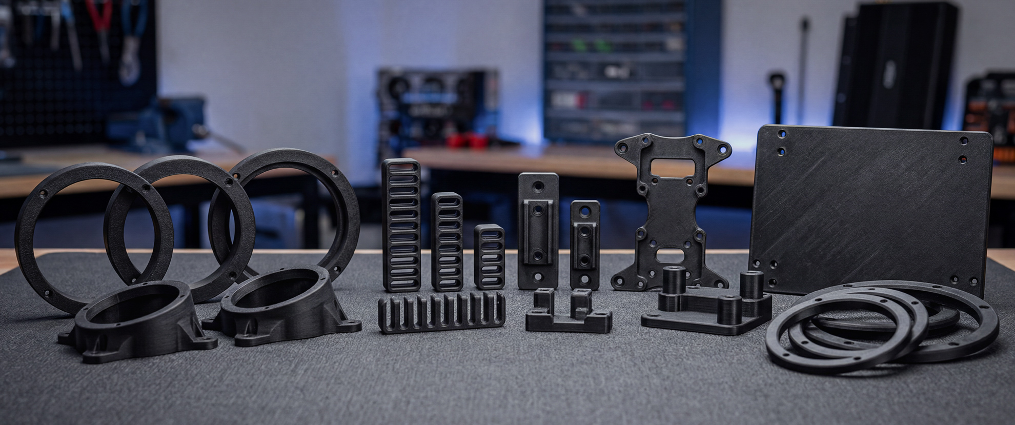
Concept visualization of planned automotive installation hardware arranged on a workbench.
Concept visualization for product-development planning. It is not current CAD or physical proof.

Company-owned development process

Eight gates between an idea and a small batch.

Hall Integrated Systems uses this process for its own automotive hardware pipeline. Each gate records what changed and what remains unverified.

  1. Define the installation problem

    Record the automotive packaging, routing, access, or mounting constraint.

  2. Document a working design decision

    Choose the current direction and state what has been deferred.

  3. Build and inspect the CAD model

    Compare visible geometry with the documented decision before calling the model complete.

  4. Measure critical interfaces and print a representative coupon

    Check cable, fastener, mounting-depth, clearance, and access inputs before the complete part.

  5. Print the complete prototype

    Document the actual material, print orientation, and resulting physical part.

  6. Evaluate fit, retention, vibration, pull, access, and serviceability

    Record only the checks actually performed and the conditions used.

  7. Record revision decisions

    Connect observed results to retained, changed, or deferred features.

  8. Prepare for a small batch

    Begin preparation only after the relevant design and validation evidence exists.

AMPLIFIER DRAWER STUDY

Physical context and concept direction stay distinct.

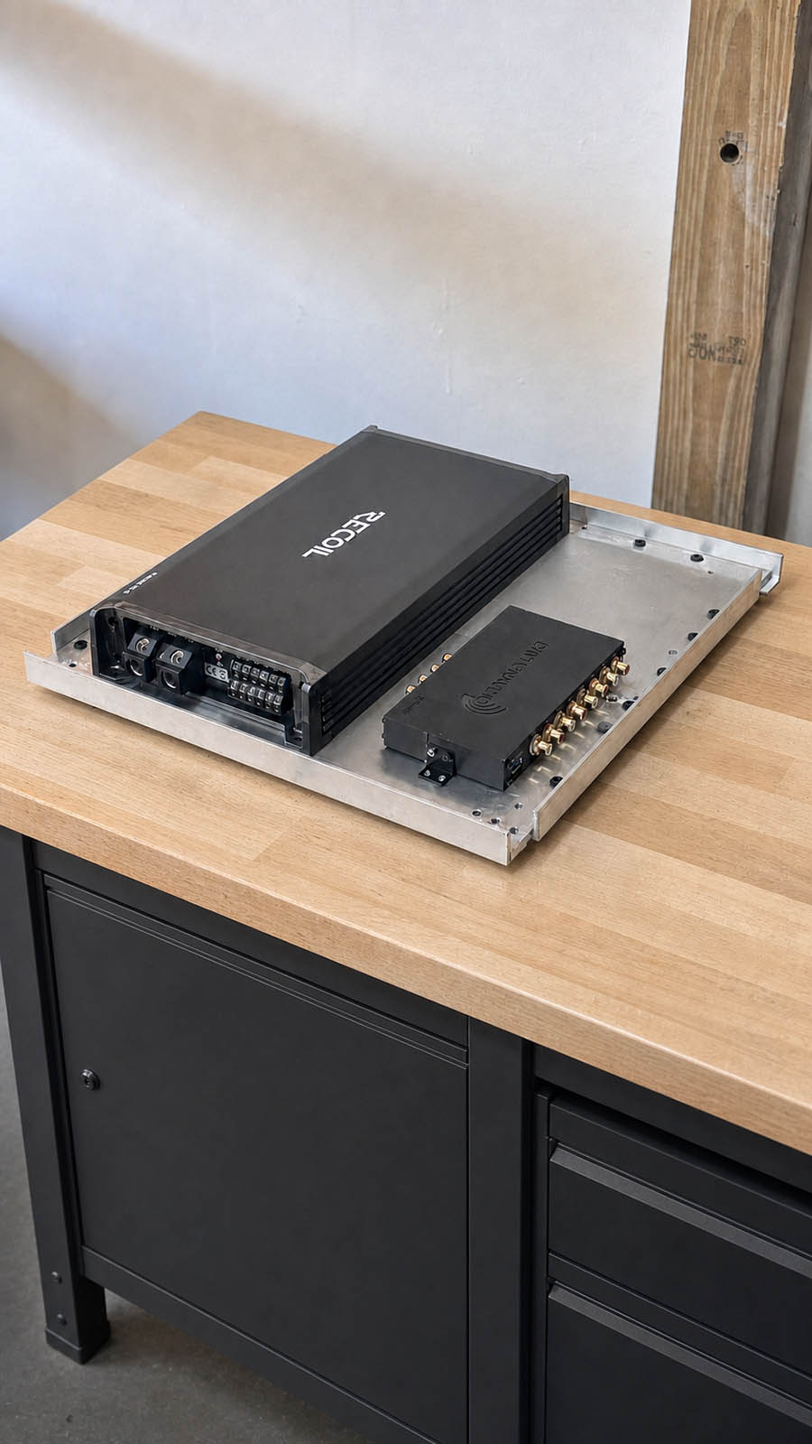
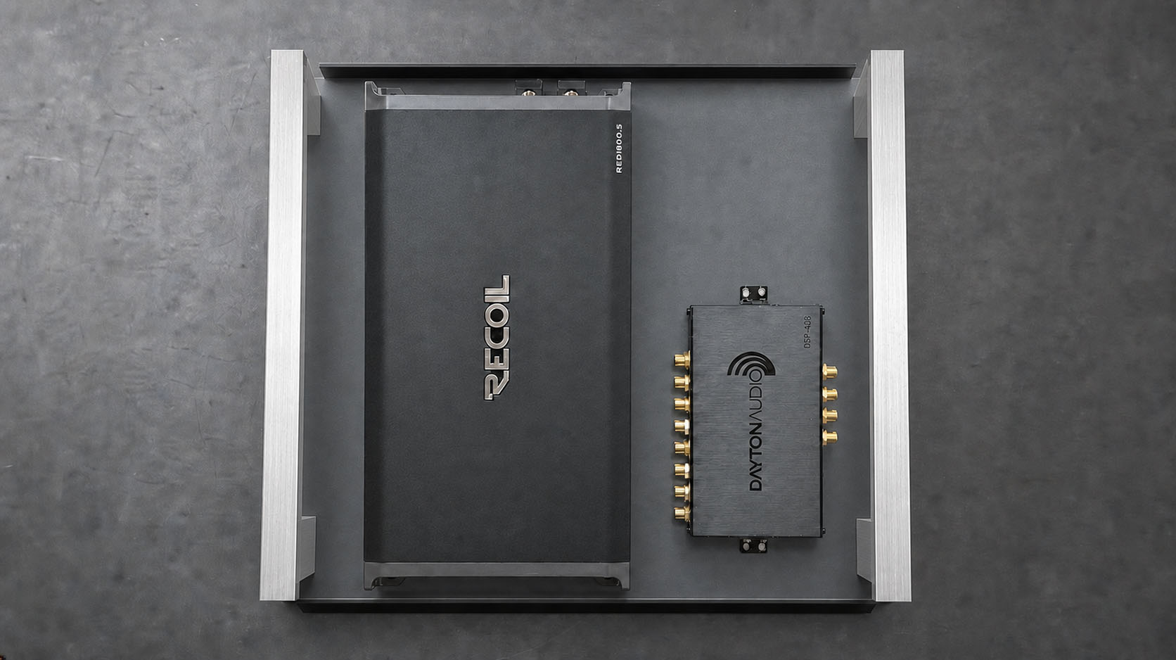
The photographed amplifier and DSP mounting work supplies real context. A separate visualization explores shallow tray geometry without presenting it as a completed or validated product.

AI-assisted visualization of a shallow amplifier and DSP drawer with raised aluminum side rails.
Functional concept visualization

AI-assisted visualization based on the photographed electronics and Hall Product Studio drawer concept.

Three-quarter photographed view of a prototype amplifier and DSP mounting drawer on a workbench.
Supporting photograph

AI-assisted retouch of the photographed prototype from a supporting workbench angle. Tiny printed labels are not specification references.

DEVELOPMENT FOCUS

Hardware for cleaner, more serviceable installs.

Route

Cable combs and clips for organized speaker and accessory wiring paths.

Fit

Speaker spacers and trim directions shaped by vehicle-specific constraints.

Mount

Bases, platforms, standoffs, and brackets for secure electronics placement.

Revise

Documented movement from working decision to CAD, print, evaluation, and the next revision.

PRODUCT ROADMAP

See where the active product sits today.

Review HIS-CA-001A, its current evidence, and the product directions queued behind it.

Explore products in development